
2.1 Application interface scenario
2.3.3.1 Public Key Infrastructure
2.3.5 Policy Enforcement Point
4.2.1 Create the directory structure
4.2.3 Generate the Private key of the RootCA:
4.2.4 Generate the RootCA's certificate
4.2.6 Copy the certificate to the place
configured within openssl.cnf
4.2.7 Link the RootCA's certificate within the
directory structure configured in openssl.cnf
4.2.8 Generate the ServerCA and UserCA and
generate the Private Key for the Server CA
4.2.9 Generate the certificate request (to be
signed from the RootCA later)
4.2.10 Sign the certificate request
4.2.11 Copy the ServerCA certificate to the place
configured within openssl.cnf
4.2.12 Repeat the last steps to create the UserCA
4.2.13 Create Browser compatible certificate files
4.2.14 Generation of a server certificate
4.2.15 Generation of a user certificate
4.2.16 Export keys and certificates to the PKCS#12
format
4.2.17 Configuration of the JSSE trust manager
4.3.1.3 RoleAssignmentPolicy(Set)
4.3.2.1.2 Add PermissionPolicies to a role
4.3.2.1.3 Add Permissions to a PermissionPolicy
4.3.2.1.4 Add Conditions to Permissions
4.3.2.2.1 Remove users from a role
4.3.2.2.2 Remove PermissionPolicies from a role
4.3.2.2.3 Remove Permissions from a PermissionPolicy
4.3.2.2.4 Remove Conditions from a Permission
4.3.2.2.5 Remove roles completely
4.3.2.2.6 Remove domains completely
4.3.3.2 Domain (-D, --Domain <label list>)
4.3.3.3 User (-U,--User <cert file list>)
4.3.3.4 targetAction (-z,--targetAction <datatype-
matchfunc[value]>)
4.3.3.5 targetResource (-y,--targetResource <datatype-
matchfunc[value]>)
4.3.3.6 Role (-R,--Role
<label list>)
4.3.3.7 PermissionPolicy (-P,--PermissionPolicy <label
list>)
4.3.3.8 -p,--Permission <list of labels>
4.3.3.9 -C,--Condition <list of labels>
4.3.4 Target syntax scheme description
4.3.5 Condition syntax scheme description
4.5.1.4 Combining algorithms deny-overrides vs.
permit-overrides
5.1 Browser Certificate Installation
1 Preface
This document contains the software documentation for the
implementation of the BioCASE rights management and access control component.
Mainly based on the standards eXtensible Access Control Markup Language (XACML)
Version 2.0 [MOS05] and XML-Signature Syntax and Processing (XML-DSIG) the
implemented software components provide an application level firewall working
on the BioCASE protocol. The components realise task like user authentication,
authorisation, role based access control, access rights management, content
signing and a simple client API. The software is completely implemented in
Java.
The following sections
describe the software implementation. First, an overview of the general system
architecture is given. Next, the system requirements are presented followed by
the user documentation. The latter comprises the configuration and usage of the
different software components and its integration within the BioCASE scenario.
Then, the installation procedure is described including the example scenario.
Finally, a reference to the developer documentation is given.
2
System Architecture
The starting point of the system architecture represents the current BioCASE scenario. Within this scenario, the client uses a common web browser to control a BioCASE application located at the provider's web server (see figure 1). This application communicates with the PyWrapper whenever access to the provider's Unit Database is required. Usually, the PyWrapper also runs on this web server.
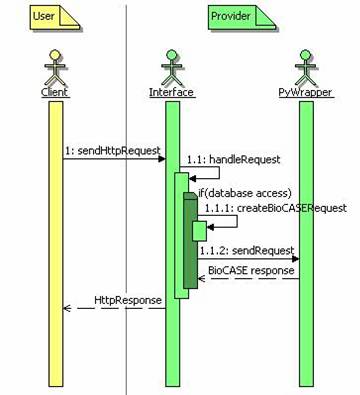
figure 1 Overview primary
BioCASE protocol
To realise authentication and access rights management, an additional access control layer was introduced, filtering the communication between the client and the application. So, the filter acts like an, so called, application level firewall. This means, it scans the client-provider communication for relevant BioCASE protocol messages and evaluates correspondent access control policies defined according to the RBAC Profile of XACML v2.0 [A05].
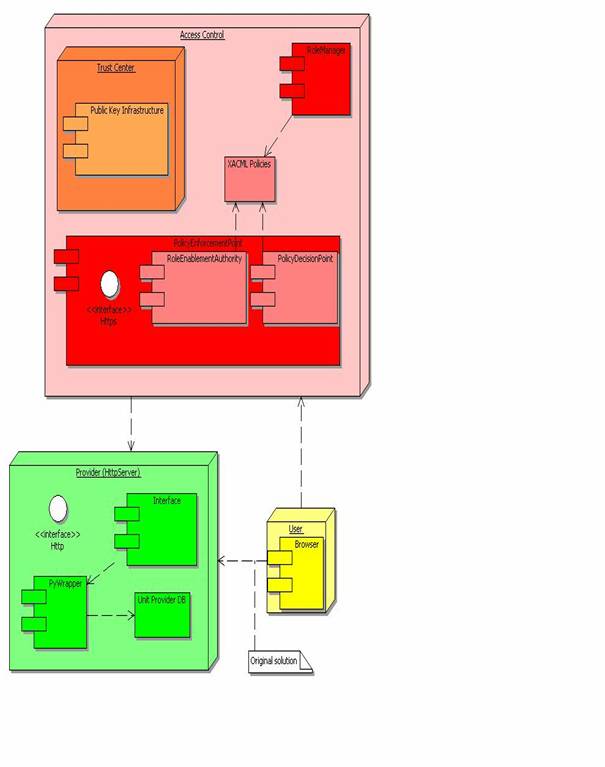
figure 2 Overview system components
This may result in blocking client BioCASE requests completely or filtering out XML elements of the content of the provider's BioCASE response on a permitted client request. Any permitted request is redirected unchanged to the relating BioCASE provider host. Further, the implementation of the access control layer founds on several components sub dividable to handle the two main tasks authentication and access rights management (see figure 2). First, there is the Trust Center component responsible for the management of the Public Key Infrastructure (PKI). The main task of the provider’s Trust Center is the issuance of certificates required for the mutual authentication between clients and servers. Second, the Policy Enforcement Point (PEP) realises the application level firewall functionality and enforces a set of XACML based role bases access control policies defined by the provider. To support system administrators managing these policies, the Role Manager component was introduced.
For security reasons, it is very important
to emphasize, that it must be assured, that the provider's web server can not
be reached from the internet or other unauthorised networks directly. The only
access point to outside clients should be the Policy Enforcement Point.
Otherwise, any of the measures to implement authentication and access control
mechanisms may be bypassed easily by communicating with the provider
application directly.
The implemented components are described in
more detail in the following sections. Meanwhile, two scenarios for the access
control layer may come into operation, the application interface scenario, and
the client API scenario. Both are enlightened in the next two sections.
2.1 Application interface scenario
This next paragraph describe the application interface scenario. The two figures figure 1 and figure 3 illustrate the components interactions of the original BioCASE protocol and the access control enhanced system architecture described below.
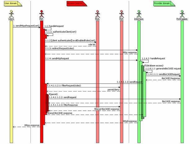
figure 3 Overview access
control enhanced BioCASE protocol
Within the original scenario (see figure 1) the user selects the URL of the provider's
application web interface in his browser. Clicking on an interactive element, such
as a button, he sends an Http-request to the web server, which is handled by
the application interface. Whenever the request requires access to the
provider's unit database, the interface creates an adequate BioCASE request and
sends this request to the PyWrapper. The PyWrapper queries the unit database,
builds the BioCASE response and sends this response back to the application
interface. The application interface formats a web page from this response and
returns the data to the client.
The starting point within the access
control enhanced system architecture remains the same (see figure 3), except that the URL of the provider begins with
"https". Furthermore, the client must import his certificate on his web
browser. Otherwise, the PEP assigns to him the guest role, defining minimal
access rights to the system only. In this scenario, the PEP, located at the
provider's access control layer, receives the client request. Then, the PEP
authenticates the client verifying its certificate got from the SSL handshake
with the client browser. If the client can not be authenticated, then the PEP also
assigns to him the guest role. When the client is authenticated, the PEP
requests the Role Enablement Authority (REA) subcomponent, to evaluate all
roles enabled for this client within the Role Assignment policies defined by
the provider's system administrators. Then, the PEP adds this list of client
roles and the internal URL of the PEP as parameters to the original client
request and forwards it to the provider's application interface. The
application interface proceeds the request as described for the primary BioCASE
scenario. If the interface needs to access the PyWrapper, then the interface
uses the URL received as request parameter from the PEP before. So, the
Interface connects to the PEP and sends the generated BioCASE request to him.
When no database request is required, then the application interface responds
the request from the PEP as described for the primary BioCASE scenario and the
PEP returns this response to the client.
When the PEP receives a request for the PyWrapper, its PEP subcomponent evaluates this request using the role list evaluated before (appended to the request from the interface as additional Http-request parameter). The Policy Decision Point (PDP) evaluates the BioCASE request against the defined XACML Role Permission policies for each of the evaluated roles. If the request is permitted for one of these roles, the PDP returns a permit decision to the PEP. If the request is denied, then the PEP creates a BioCASE error response and returns this response to the application interface.
Otherwise, the PEP forwards the BioCASE request unchanged to the PyWrapper. Then, the PyWrapper's BioCASE response is evaluated against the defined XACML Role Permission policies also. If the PDP denies the access to any of the sub elements or element attributes of the content of the BioCASE response, then the PDP also eliminates this element (and all its attributes and sub elements) or the attribute from the content element of the BioCASE response respectively.
Finally, the BioCASE response filtered by the PDP is returned to the provider's application interface, which proceeds the response as normal. The application interface returns its final Http-response to the PEP returning this final response directly to the client.
2.2 Client API scenario
Unlike the application interface scenario, there are only a few changes using the client API. The main change is that there is no interaction between the PEP and the application interface. The PEP receives BioCASE requests through the client API and delivers the permitted requests directly to the PyWrapper of the original BioCASE scenario. Also, the PEP receives BioCASE responses directly from the PyWrapper and delivers them to the client API.
The major task of the client API is the provision of a simple, but easy to use communication interface, which may be used by any other client application or application interface. The location of the client API should not be at the provider hosting the PyWrapper. Because in addition, the client API now supports the verification signed content document received in BioCASE responses from the PEP. The result of this verification will be reported through the addition of some Diagnostic element to the original BioCASE response. You will agree with, because it makes no sense if the provider would verify its own signature on behalf of the client user. The default application interface scenario does currently not support signature verification.
The second feature not supported within the
default application interface, is that the client API supports some kind of
single-sign-on mechanism e.g. for web portals realising their own client
authentification. Assumed, that the BioCASE provider trusts this web portal, it
accepts the identity of all clients authenticated by that trusted application.
Therefore, a special role – called trustedClient - may be assigned to
this client application in the PEP’s XACML policies permitting proxying of user
identities by passing the client identity in form of an X.509 certificate to
the PEP.
2.3
Components
The following sections describe the
components presented in the overview in more detail, such as the
· BioCASE Provider
· Public Key Infrastructure
· Web Browser
· RoleManager
· Policy Enforcement Point
· Client API
2.3.1
BioCASE Provider
To support the access control enhancements,
the original BioCASE scenario [BIO05] has been subject to some minor
modifications already suggested above. The enhanced scenario should be
supported in the provider software starting with version 2.31. This version has
been implemented for the computer demonstration at the TDWG 2005 meeting in
September 2005. The following paragraphs describe the required modifications.
First, the provider software must store the
role list sent from the PEP included since the initial request forwarded to the
application interface (see clause 4.5). The role list is sent within the Http-parameter role.
The provider interface must include this parameter to any PyWrapper request
(redirected to the PEP). This indicates to the PEP, that the request was
initiated from the PyWrapper and intended for the PyWrapper.
Next, for the redirection of PyWrapper-requests
initiated by the provider’s application interface, the PEP uses the already defined
Http-parameter wrapperURL for any Http-POST requests or url
for any Http-GET requests respectively. For that, the PEP must be
configured with its own (PyWrapper)-URL, such it can be connected from the
internal network, i.e. the web server hosting the provider's application
interface (see clause 4.1.2.3).
2.3.2
Browser
Within the BioCASE scenario, the web browser
usually serves as graphical user interface enabling the client to interact with
the provider software. To be suitable for the enhanced access control
environment, the client's web browser must support the Https-protocol (e.g. Mozilla
Firefox [MOZ05], Microsoft Internet Explorer). Furthermore, the user must
install its own X509 certificate and, to verify the authenticity of the
provider host, the certificate of the provider. Both certificates should be
available from the provider’s Trust Center.
2.3.3
Trust Center
The main task of the provider’s Trust
Center is reliable authenticity management. Therefore, the Trust Center ensures
the authenticity of entities by generating key pairs and issuing certificates
for these entities. With the issuance of certificates (see clause 4.2), it guarantees that the owner of the corresponding
private key is the entity described within the certificate's attributes. The
Trust Center must also ensure to hand out the related private key to the
correct entity. An entity may be a person, like a system user, but may also be
a system, such as the provider's Policy Enforcement Point.
Usually, a Trust Center provides further information
services allowing to query for certificates of given entities or to provide
information about the current state of a certificate (valid, revoked, and
expired) [SS04]. But in the current scenario, the Trust Center just serves as a
secure user or server registry on behalf of the provider. So, it creates key
pairs for registered clients and server hosts of this provider and issues the
corresponding certificates. Then it ensures to hand out the key pairs and
certificates to their correct owners, i.e. the registered system user or the
server administrator respectively. Finally, the provider has to publish the
relevant server certificates, such as to make possible to authenticate the
provider servers to the client. For that, the client just has to install its
private key and certificate, and the server certificates within its security
enabled web browser (e.g. Firefox, Internet Explorer).
This project provides a basic Trust Center
solution based on the OpenSSL project. The implemented Public Infrastructure
should be suitable not only for single providers, but for providers belonging
to the same security domain or hosting multiple provider databases also. The
solution should be extensible to more complex infrastructures. Very useful
information about the construction of Public Key Infrastructures gives [DFN00].
Anyway, the following section shortly describes the provided Public Key Infrastructure.
2.3.3.1
Public Key Infrastructure
The Public Key Infrastructure bases on the
X.509 standard [IET05] and realises the mutual authentication between client
and provider within the Policy Enforcement Point of the Access Control Layer
using the Secure Socket Layer (SSL) protocol. Every X.509 PKI founds on a Root
Certification Authority (RootCA), which must be at the same time the most
trustworthy and most secured entity in the whole security infrastructure. The
RootCA provides certificates for Registration Authorities (RA) thus enabled to
issue certificates for users or servers. We established two RAs: a ServerCA,
issuing certificates for provider servers and a UserCA issuing certificates for
users. Both issue certificates on request of the provider administrators, when
a new provider host shall be setup, or the provider's system administrators,
when they register a new client. The following figure illustrates the hierarchy
of the demonstration scenario, where keys and certificates for one provider and
three clients were issued. As stated above, this infrastructure may be easily
extended to support several provider or providing hosts and the addition of an
arbitrary amount of users. The definition of roles and the assignment of users
to these roles bases on the issued X509 user certificates and is supported by
the RoleManager tool.
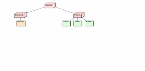
figure 4 Public Key Infrastructure
2.3.4 RoleManager
The RoleManager is a small command line
application permitting the
· definition of roles
· assignment of users to roles
· definition of permission policies
·
assignment of permission
policies to roles
· definition of permissions
· assignment of permissions to permission policies
·
assignment of conditions to
permissions
The RoleManager supports the provider's
system administrators to manage and configure an adequate XACML policy
hierarchy according to the XACML Role Based Access (RBAC) profile [A05]. The
detailed commands and parameters are described in clause 4.3.2. The policies defined with the RoleManager are stored
as XML files in a special configuration directory on the file system (see
clause 4.1.1). Configured with the same policy directory location,
the Policy Enforcement Point (PEP) and its subcomponents Role Enablement
Authority (REA) and Policy Decision Point (PDP) evaluates the enabled roles or
access rights for a given action and resource from these policy files
respectively.
2.3.5 Policy Enforcement Point
As its name suggests, the Policy
Enforcement Point (PEP) represents the system entity enforcing authentication
and access control on behalf of a given provider. Thereby, the PEP becomes the
only access point to the provider's application interface and/or PyWrapper
respectively.
To realise the authentication, the PEP
accepts all incoming requests on behalf of the provider using the SSL-protocol
(https). For the realisation of the Role Based Access Control, the PEP involves
two subcomponents:
· Role Enablement Authority (REA)
· Policy Decision Point (PDP)
The REA's task is to evaluate a list of
enabled roles for a given client identified by its X.509 certificate. The REA
is a special instance of an XACML PDP, focusing on Role Assignment Polices only
(see clause 4.3.1) and specifying user-to-role assignments. To process
the request the REA requires a X.509 certificate. The REA evaluates all roles
specified within the Role Assignment Policies and evaluates for each role, if
this role is enabled for the client authenticated by the given X.509
certificate. Finally, the REA returns the resulting list to the requester, i.e.
the PEP.
If the authentication of the client fails,
then the PEP creates a role set containing the predefined role guest only.
The PDP's task is to evaluate access rights for a given set of roles, on a given resource with a given action. Therefore, the PDP just focuses on Role Policy Sets, referencing the Permission Policies defined for a given role (see clause 4.3.1). Permission Policies include of a set of Permissions specifying resources enabled for a given action. Thus, the same policies can be referenced from different roles.
Within the BioCASE environment, we have to
distinguish request and response policies. Within request policies, resources
are defined as paths to concepts, which may be subject of a scan or search
request. Unlike request policies, resources are defined as paths to elements or
attributes within the XML document included in the content sub element of a
BioCASE response. Actions are defined on each of the specified BioCASE protocol
method, such as capabilities, scan and search. To allow
the definition of permissions for requests and responses, the suffixes "-request"
or "-response" has to be appended to the method names within Permissions.
So, the PDP needs at least a role, a resource and the related BioCASE request
method to evaluate if access to the given request or a response content element
may be granted or not.
After a successful client authentication,
the PEP gets the client's certificate and queries the REA for the set of
enabled roles. When receiving a request designated to the PyWrapper, the PEP
analyses this BioCASE request and generates an evaluation request to the PDP
with the role set evaluated by the REA as subject, the requested concept(s) as
resource(s) and the request method as action. If the PDP permits the request,
the PEP forwards the request to the PyWrapper. After receiving the BioCASE
response from the PyWrapper, the PEP examines the resulting content document
and creates an evaluation request to the PDP with the role set as subject and
the response method as action for each element or attribute path in this
content document. If the PDP does not permit the access to any of the content's
sub elements, then the PEP eliminates this element and all its attributes and sub
elements from the BioCASE response. If access is denied for an attribute, the
PEP eliminates this attribute only.
More details about the integration of the PEP in the BioCASE protocol have been described in the clause 4.5).
2.3.6 Client API
The main objective of the client API is the communication management with the Policy Enforcement Point (PEP) of a BioCASE provider. The API may be used to provide security related facilities like authentication or signature verification within any third party BioCASE application interface.
The client API was implemented in Java, where the main interface was realised in the class nbi.xmlsec.PEPClient. It can be used to send and receive requests and responses of the BioCASE protocol. Further, it supports SSL authentication against the PEP and the signature verification of possibly signed content documents within BioCASE responses. The result of the verification process is reported within the Diagnostics of the original BioCASE response. Therefore, the newly create code attribute “SECURITY”is used.
Finally, the classes of the package nbi.xmlsec.biocase.protocol
(e.g. Request, Response) provide an easy to use interface to create and
evaluate BioCASE request and responses respectively.
3
System Requirements
The following sections include an overview
of the system requirements needed to install and run the software. Currently
the following third party or open source components are indispensable to run
the system:
· Java OS
· OpenSSL
· Ant
· bash-shell
The Java section also contains a list of
open software projects, which libraries have been used to implement the system.
3.1 Java Platform
The software implementation builds up on
the Java 2 Platform, Standard Edition (J2SE) Version 1.4.2 [SUN05]. The current
release number is 10. Furthermore, the Java Cryptography Extension (JCE)
Unlimited Strength Jurisdiction Policy Files 1.4.2 are required, enabling to
use third party JCE provider on the Java Platform.
The Java Platform is available for all
popular Windows, Linux and Solaris operating systems. Using the Java Platform,
the software implementation uses the following open source third party software
components:
|
Bouncy Castle JCE provider |
[TAU05] |
|
Sun's XACML Implementation |
[SUN04a] |
|
Jetty Java Http Servlet Server |
[MOR05] |
|
Apache Jakarta Subproject Commons components: - CLI - Collection - Configuration - IO - Lang |
[THE05a] |
|
Log4j project |
([APA05]) |
|
JSR-105 XML Digital
Signature APIs |
[SUN04b] |
See the installation guide (see clause 5) for further information.
3.1.1
OpenSSL
The OpenSSL Project [THE05b] offers an Open
Source implementation of the Secure Sockets Layer (SSL)/Transport Layer Security
(TLS) protocol and a general purpose cryptography library. OpenSSL is used in
this system to provide the Trust Center functionality such as the generation of
Public Key pairs and X.509 certificates.
Binary distributions of OpenSSL are
included in most popular Linux distributions and for Microsoft Windows. During
the implementation of this system, the OpenSSL package included in Cygwin (see clause
3.1.2) was used to build up a test PKI. In the course of
the development, some a basic OpenSSL configuration has been developed,
supporting the creation of the PKI (see 4.2).
3.1.2 Cygwin
Cygwin is a Linux-like environment for
Windows providing a collection of useful Linux/Unix tools like the bash-shell
or the OpenSSL package [RED05]. The software distribution contains some useful
bash-scripts to install the software and run the PEP and RoleManager
application. Thus, the software should run under the Windows Operating System,
it could be time-saving to start working with Cygwin first.
3.1.3
Ant
The Apache Ant Project [THE05c] provides a Java-based build tool. Ant is used within this project to
· compile a distribution zip-file
· compile the distribution's source code
·
generate the JavaDoc-based
developer documentation from the distribution's source files
·
install the software from the
unzipped distribution
It is quite comfortable to use ant from the
eclipse platform IDE [ECL05]. Anyway, refer to the project pages for current
installation instructions.
3.1.4
BioCASE Provider
Of course, to see the system working, a
BioCASE provider is needed. The system should cooperate with the BioCASE
provider version 2.3.1 [BIO05]. This is the version used for the computer demonstration
at the TDWG 2005 Meeting in September 2005. If the version is not available on
the web page, please contact the BioCASE developers for support.
3.1.5
Web Browser
The web browser is required to drive the
provider's application interface and manage the Public Key Pair of the client
and the certificates of the provider host running the PEP during the
authentication. The web browser of choice must support the https protocol,
X.509-certificates and PKCS#12 key pair files. The software has been developed
using the Mozilla Firefox Browser version 1.0x [MOZ05] and has been tested with
the Microsoft Internet Explorer version 5.x or higher included in Windows XP.
4 User Documentation
This section of the document contains the
user documentation of the implemented system components. It shall support
system administrators to configure the software and define XACML policies. The
documentation starts with a description of the configuration issues of the
implemented components. Then it explains the policy management structures and
shows how to set up the PKI using OpenSSL. Next it provides a user manual of
the Role Manager component and concludes with a detailed description of the
BioCASE system integration of the PEP.
4.1 Configuration (general)
The configuration of the RoleManager, the
Policy Enforcement Point and the Role Enablement Authority is build up on the
subproject Commons Configuration of the Apache Jakarta Project
(http://jakarta.apache.org/commons/configuration/). The configuration consists
of the file "config.xml" specifying the configuration objects to
load. We decided to use an XML based configuration object, which is stored in
an XML file to be configured within the attribute "fileName" of the
element "xml" in the config.xml.
<?xml version="1.0"
encoding="ISO-8859-1" ?>
<configuration>
<xml fileName="PEPconfig.xml"/>
</configuration>
Currently, there is not DTD or XML schema
to describe the format, neither from the Commons Configuration project, nor
from us. So, the relevant parameters will be explained in the configuration
sections of the correspondent component. (see clauses 4.1.1, 4.1.2 and 4.1.2.5).
Generally, the root element is ignored, so
the configuration of a component starts with its corresponding element name
such as RoleManager, PolicyEnforcementPoint or RoleEnablementAuthority.
4.1.1 RoleManager
The configuration largely represents the class
architecture of the RoleManager's software architecture. The aim of the RoleManager's
configuration framework is to keep the configuration of the RoleManager's
components as flexible as possible. So, any of the particular components
implementing classes may be interchangeable whenever wanted.
The RoleManager element has two attributes:
|
RoleManager |
|
|
Attribute |
Function |
|
class |
The class of the RoleManager
implementation to be loaded. |
|
defaultDomain(required) |
The default domain specifies the
domain to be used, when the command line interface is invoked without the -D
option. |
Furthermore, the RoleManager element must
contain a PolicyManager element described in clause 4.1.2.5.1.
As an example, look at the example
RoleManager configurations delivered with this distribution (see also clause 5.5).
<RoleManager
class="nbi.xmlsec.xacml.profile.rbac.RoleManager"
defaultDomain="biocase" >
<PolicyManager
class="nbi.xmlsec.xacml.profile.rbac.PolicyManager"
policyBaseDir="./policies">
<PolicyFinder>
<PolicyFinderModule
class="nbi.xmlsec.xacml.profile.rbac.finder.RBACPolicyFinderModule"
policyBaseDir="./policies" >
<SuffixFileFilter>.xml</SuffixFileFilter
>
</PolicyFinderModule>
</PolicyFinder>
</PolicyManager>
</RoleManager>
If the specification of any class attribute
is omitted, the implementation loads the default classes of this distribution. Anyway,
for comfort reason you should define the default domain and the policyBaseDir
within the PolicyManager element as default values. Otherwise, you will be
forced to state the options -D and --policyBaseDir in every command
invoked (see clause 4.3.2).
4.1.2 PolicyEnforcementPoint
The configuration largely represents the
configurable objects of the PolicyEnforcementPoint's software architecture. The
aim of this configuration framework is to keep the configuration of the
components as flexible as possible. So, any of the particular components
implementing classes may be interchangeable whenever wanted.
The PEP element has one optional attribute:
|
/PEP |
|
|
Attribute |
Function |
|
class |
The class of the PEP implementation to
load |
Furthermore, the RoleManager element must contain a Filter element. The Filter implements the filtering of incoming requests and responses. Currently, this filter builds up on the HttpServer implementation of the Jetty Project [MOR05].
|
/PEP/Filter |
|
|
Attribute |
Function |
|
class |
The class of the PEP implementation to
load |
Thus, Jetty's software architecture
determines the items to be configured, such as
· Context path
· Listener
· Handler
The context path simply specifies the path
on the HttpServer, where the PolicyEnforcementPoint is attached. The Listener
waits for connections on a specific IP-address and port and needs SSL
parameters to be specified. Finally, the handler processes the incoming Http-
requests and responses and therefore sets up the Role Enablement Authority and
Policy Decision Point used to grant access or not.
4.1.2.1
Context Path
The context path simply specifies the path
on the HttpServer, where the PolicyEnforcementPoint to be attached. If the
context path is set to "\", then the PEP is accessible on the root
level of the server.
The ContextPath element has the following attribute:
|
/PEP/Filter/Context |
|
|
Attribute |
Function |
|
path |
The path of the PEP on the server |
4.1.2.2
Listener
The Listener awaits connections to the PEP.
To do that, a host name and port number must be configured. The default
scenario provides the SSL protocol for the authentication of users and to
protect the connection against tampering. Therefore, the Listener contains a sub
element SSL, where specific parameters such as a key store, containing the
private key of the PEP, its type and passwords for the key and key store may be
specified.
The Listener element has the following attributes:
|
/PEP/Filter/Listener |
|
|
Attribute |
Function |
|
class |
The class of the Listener implementation
to load |
|
host |
The PEP's host name |
|
port |
The PEP's port number |
The Listener's SSL sub element has the following attributes:
|
/PEP/Filter/Listener/SSL |
|
|
Attribute |
Function |
|
needClientAuth |
Client must be authenticated |
|
wantClientAuth |
Client authentication is not
obligatory |
Furthermore, the SSL element has the sub elements KeyStore and Key. The element KeyStore defines the key store, where the private key of the PEP is stored into. It has the following attributes:
|
/PEP/Filter/Listener/SSL/KeyStore |
|
|
Attribute |
Function |
|
file |
The key store’s file path |
|
type |
The type of the key store (e.g.
PKCS12) |
|
password |
The password needed to access the key
store |
The element Key only specifies the password for the PEP's private key.
|
/PEP/Filter/Listener/SSL/Key |
|
|
Attribute |
Function |
|
password |
The password needed to access the
PEP's private key |
Finally, the Listener's sub element ThreadPool allows to define the minimum and maximum amount of threads started by the Listener to serve requests. This can be configured with the following attributes:
|
/PEP/Filter/Listener/ThreadPool |
|
|
Attribute |
Function |
|
minThreads |
The minimum number of threads to be
started |
|
maxThreads |
The maximum number of threads to be
started |
4.1.2.3
Handler
The handler proxies incoming Http-requests and responses and act's like an application level firewall by blocking requests and filtering the content of responses returned from the BioCASE provider.
|
/PEP/Filter/Handler |
|
|
Attribute |
Function |
|
class |
The class of the Handler
implementation to load |
|
domain |
The domain specifies the domain to be
used in PDP requests. |
To communicate with the provider, the
handler needs the URLs of the provider's application interface and database
wrapper. This may be done within the sub elements Proxy and Wrapper.
The Handler's sub element Proxy has the following attributes:
|
/PEP/Filter/Handler/Proxy |
|
|
Attribute |
Function |
|
url |
The url of the provider's application
interface |
The Handler's sub element Wrapper has the following attributes:
|
/PEP/Filter/Handler/Wrapper |
|
|
Attribute |
Function |
|
url |
The url of the provider's database
wrapper |
To enable the PEP handler for signing BioCASE responses, the handler needs access to a private key. Analogous to the Listener’s SSL configuration (see clause 4.1.2.2), this will be done using the subelements KeyStore and Key. So, the same or different keys may be used for authentication and signing.
|
/PEP/Filter/Handler/KeyStore |
|
|
Attribute |
Function |
|
file |
The key store’s file path |
|
type |
The type of the key store (e.g.
PKCS12) |
|
password |
The password needed to access the key
store |
The element Key only specifies the password for the PEP's private key.
|
/PEP/Filter/Handler/Key |
|
|
Attribute |
Function |
|
password |
The password needed to access the
PEP's private key |
The sub elements RoleEnablementAuthority and PolicyDecisionPoint are largely configured by the specification of their classes and the configuration of their policy managers. Thus, both consist of the following attribute:
|
/PEP/Filter/Handler/RoleEnablementAuthority and PDP |
|
|
Attribute |
Function |
|
class |
The class of the RoleEnablementAuthority
or PolicyDecisionPoint implementation to load respectively |
Both include the sub element PolicyManager
to configure the policies to be included within the policy evaluation
processes. The configuration of the PolicyManager describes clause 4.1.2.5.1.
4.1.2.4 Example
As an example for the complete configurations
of the PEP component, look at the PEP’s example configuration part delivered
with this distribution (see also clause 5.5).
<PolicyEnforcementPoint
class="nbi.xmlsec.PEP">
<Filter class="org.mortbay.http.HttpServer">
<Context path="/" />
<Listener
class="org.mortbay.http.SslListener" host="localhost"
port="443">
<SSL needClientAuth="false"
wantClientAuth="true">
<KeyStore
file="./keystore.p12" type="PKCS12"
password="provider" />
<Key
password="provider" />
</SSL>
<ThreadPool minThreads="5"
maxThreads="100" />
</Listener>
<Handler class="nbi.xmlsec.PEPHandler"
domain="biocase">
<KeyStore
file="./keystore.p12" type="PKCS12"
password="provider" />
<Key alias="BioCASE Provider 2048 Bit Zertifikat"
password="provider" /> <Proxy
url="http://localhost:8080" />
<Wrapper
url="https://localhost" />
<RoleEnablementAuthority
class="nbi.xmlsec.xacml.profile.rbac.RoleEnablementAuthority">
<PolicyManager
class="nbi.xmlsec.xacml.profile.rbac.PolicyManager"
policyBaseDir="./policies" >
<PolicyFinder
>
<PolicyFinderModule
class="nbi.xmlsec.xacml.profile.rbac.finder.RBACPolicyFinderModule" policyBaseDir="./policies"
>
<SuffixFileFilter
>.xml</SuffixFileFilter >
</PolicyFinderModule>
</PolicyFinder
>
</PolicyManager>
</RoleEnablementAuthority>
<PDP
class="nbi.xmlsec.xacml.profile.rbac.RBACPDP">
<PolicyManager
class="nbi.xmlsec.xacml.profile.rbac.PolicyManager"
policyBaseDir="./policies" >
<PolicyFinder
>
<PolicyFinderModule
class="nbi.xmlsec.xacml.profile.rbac.finder.RBACPolicyFinderModule"
policyBaseDir="./policies" >
<SuffixFileFilter
>.xml</SuffixFileFilter >
</PolicyFinderModule>
</PolicyFinder
>
</PolicyManager>
</PDP>
</Handler>
</Filter>
</PolicyEnforcementPoint>
4.1.2.5
Policy Management
The policy management is processed by the
component PolicyManager, which must be configured to identify the policies to
be included within the policy evaluation processes. This is done by the
subcomponents PolicyFinder and FileFilter. The following sections describe their
configurations.
4.1.2.5.1
PolicyManager
The PolicyManager's objective is to keep track of all defined policy types and may be described the following attributes:
|
PolicyManager/ |
|
|
Attribute |
Function |
|
class |
The class of the PolicyManager
implementation to load |
|
policyBaseDir |
The path to the base directory, where
the policy file structure is located |
.
Next, the PolicyManager element must
contain a PolicyFinder element.
4.1.2.5.2 PolicyFinder
The PolicyFinder is used by the SunXACML library to retrieve the policies to be evaluated. For that, the policy finder has to specify at least one PolicyFinderModule, which does that work for him. Each policy finder module is configured through a PolicyFinderModule element and has the following attributes:
|
PolicyManager/PolicyFinder/PolicyFinderModule |
|
|
Attribute |
Function |
|
Class |
The class of the PolicyFinder module implementation
to load |
|
policyBaseDir |
The path to the base directory, where
the policy file structure is located |
The policy base directory defined here
replaces any previously configured, higher-levelled policyBaseDir definition
(e.g. within the PolicyManager's configuration.
Additionally, each PolicyFinderModule may
contain several FileFilter elements, filtering out the files to be identified
as policy files.
4.1.2.5.3 FileFilter
A FileFilter filters out the files to be
identified as policy files. Currently, only a SuffixFileFilter is implemented,
but this feature may be extended in future versions.
The value of a SuffixFileFilter determines the suffix of matching filenames, such as ".xml".
|
PolicyManager/PolicyFinder/PolicyFinderModule/(Suffix)FileFilter |
|
|
Attribute |
Function |
4.1.2.5.4 Example
As an example, look at the example PolicyManager
configurations delivered with this distribution (see also clause 5.5).
<PolicyManager
class="nbi.xmlsec.xacml.profile.rbac.PolicyManager"
policyBaseDir="./policies" >
<PolicyFinder>
<PolicyFinderModule
class="nbi.xmlsec.xacml.profile.rbac.finder.RBACPolicyFinderModule"
policyBaseDir="./policies" >
<SuffixFileFilter
>.xml</SuffixFileFilter >
</PolicyFinderModule>
</PolicyFinder >
</PolicyManager>
4.2 Public Key infrastructure
All client identification issues base on an
X509-Public Key Infrastructure (PKI). The following sections describe how to
build up a PKI consisting of a RootCA and the RA's ServerCA to register servers
and UserCA to register users (see clause 2.3.3.1). Furthermore, the generation of server and user
X.509 certificates is explained and the prepare key and certificate files to be
imported by browsers.
The software distribution contains a
subdirectory CA, where the OpenSSL configuration file openssl.cnf
should be found. This file (and this how to too) assumes, that CA is the
current working directory where OpenSSL is called. All preconfigurations in openssl.cnf
are defined relative to that directory. In particular, the distribution should
have created the directory structure. If not, the following directory structure
should be created. The examples below are created using the Cygwin bash-shell.
4.2.1 Create the directory structure
Create the subdirectories RootCA, ServerCA
and UserCA within the CA directory (command mkdir). Copy the openssl.cnf
file into the CA directory (command cp). Then, the directory listing
should look like this:
$ ls -la CA
total 8
drwxr-xr-x+ 5 lusu None 0 Mar 21 11:07 .
drwx------+ 7 lusu None 0 Mar 21 10:20 ..
drwxr-xr-x+ 6 lusu None 0 Mar 21 11:06 RootCA
drwxr-xr-x+ 6 lusu None 0 Mar 21 11:07 ServerCA
drwxr-xr-x+ 6 lusu None 0 Mar 21 11:07 UserCA
-rwxr-xr-x 1 lusu None 7730 Mar 21 11:03 openssl.cnf
In each subdirectory (RootCA, ServerCA
and UserCA) create the subdirectories certs, crl, newcerts
and private. Additionally, create the file index.txt and serial
using the following commands:
$ touch ...CA/index.txt
$ echo "01" >...CA/serial
Now, the content of each subdirectory
should look as follows
$ ls -la CA/RootCA
total 1
drwxr-xr-x+ 6 lusu None 0 Mar 21 11:06 .
drwxr-xr-x+ 5 lusu None 0 Mar 21 11:07 ..
drwxr-xr-x+ 2 lusu None 0 Mar 21 10:48 certs
drwxr-xr-x+ 2 lusu None 0 Mar 21 10:48 crl
-rw-r--r-- 1 lusu None 0 Mar 21 11:06 index.txt
drwxr-xr-x+ 2 lusu None 0 Mar 21 10:48 newcerts
drwxr-xr-x+ 2 lusu None 0 Mar 21 11:17 private
-rw-r--r-- 1 lusu None 3 Mar 21 11:04 serial
Finally, is it possible to create own
random files for each CA creating the file .rand in each subdirectory private
of each of CA subdirectories (RootCA, ServerCA and UserCA).
If it is not present, OpenSSL will create own random numbers during key
generation. When done, each private subdirectory should look like this:
$ ls -la CA/RootCA/private
total 3
drwxr-xr-x+ 2 lusu None 0 Mar 21 11:17 .
drwxr-xr-x+ 6 lusu None 0 Mar 21 11:06 ..
-rw------- 1 lusu None 1024 Mar 21 10:47 .rand
4.2.2 Adopt openssl.cnf
There are only a few points where
modifications should be taken without being confident with the configuration of
the OpenSSL software. For other modifications, please refer to the official
OpenSSL documentation [THE05b] or [DFN00].
Set the $HOME variable within
openssl.cnf or the CA_HOME environment variable (export
CA_HOME /some_dir using bash) to an absolute
path, if OpenSSL is usually called from another working directory than CA.
Set the default_ca variable in the section [ca]
to e.g. UserCA, if the keys and certificates for the ServerCA and
UserCA are created, and only user key pairs and certificates shall be
created.
Adopt the default values proposed during the generation of a certificate's X.500 Distinguished Name, so that they are suitable for your organisation. This may be done within the section [req distinguished name] changing the entries with the suffix _default.
4.2.3 Generate the Private key of the RootCA:
The following command creates a 2048 bit
RSA Private Key for the RootCA. OpenSSL requests to enter a pass phrase for the
key. Remember that pass phrase, but keep that secret very safe!
$ openssl genrsa -aes256 -out
RootCA/private/RootCA.key.pem -rand RootCA/private/.rand 2048
1024 semi-random bytes loaded
Generating RSA private key, 2048 bit long modulus
...................+++
.....................+++
e is 65537 (0x10001)
Enter pass phrase for RootCA/private/RootCA.key.pem: (your_pw)
Verifying - Enter pass phrase for RootCA/private/RootCA.key.pem: (your_pw)
4.2.4 Generate the RootCA's certificate
The following command creates a self-signed
certificate of the RootCA, valid for five years and with the serial number 0.
Therefore, OpenSSL requests to enter the pass phrase of the RootCA's private
key. The proposed values for the Distinguished Name may be modified. Anyway, a
unique Common Name must be entered.
$ openssl req -config ./openssl.cnf
-set_serial 0 -new -x509 -days 1827 -key RootCA/private/RootCA.
key.pem -out RootCA/RootCA.cert.pem
Enter pass phrase for RootCA/private/RootCA.key.pem:
You are about to be asked to enter information that will be incorporated
into your certificate request.
What you are about to enter is what is called a Distinguished Name or a DN.
There are quite a few fields but you can leave some blank
For some fields there will be a default value,
If you enter '.', the field will be left blank.
-----
Country Name (2 letter code) [DE]:
State or Province Name (full name) [Berlin]:
Locality Name (eg, city) [Berlin]:
Organization Name (eg, company) [FU-Berlin]:
Organizational Unit Name (eg, section) [NBI]:
Common Name (eg, YOUR name) :RootCA NBI
Email Address :
4.2.5 Verify the certificate
$ openssl x509 -in
RootCA/RootCA.cert.pem -text
4.2.6 Copy the certificate to the place configured within openssl.cnf
The location of the certificate is
indicated within the section [RootCA] in the variable certificate, the
location of the private key in the variable private_key:
certificate =
$dir/cacert.pem
private_key = $dir/private/cakey.pem
Now, copy both files to the right location.
$ cp RootCA/RootCA.cert.pem
RootCA/cacert.pem
$ cp RootCA/private/RootCA.key.pem RootCA/private/cakey.pem
4.2.7 Link the RootCA's certificate within the directory structure
configured in openssl.cnf
The certificate must be copied in the
RootCA's subdirectory certs, renamed with the serial number and linked
with its hash value:
$ cp RootCA/RootCA.cert.pem
RootCA/certs/00.pem
$ cd RootCA/certs/
$ ln -s 00.pem `openssl x509 -hash -noout -in 00.pem`.0
Now, the certificate of the RootCA is ready
for working. Continue creating the Registration Authorities for servers und
users, ServerCA and UserCA.
4.2.8 Generate the ServerCA and UserCA and generate the Private Key for
the Server CA
The generation of a key pair is analogous
to the RootCA. You will also be requested to enter a pass phrase. Remember it
and keep it secret!
$ openssl genrsa -aes256 -out
ServerCA/private/ServerCA.key.pem -rand /usr/lib/ssl/ServerCA/private/.rand
2048
4.2.9 Generate the certificate request (to be signed from the RootCA
later)
The following command creates a certificate
request for the ServerCA to be signed from the RootCA later. Therefore, OpenSSL
requests to enter the pass phrase of the ServerCA's private
key. The proposed values for the Distinguished Name may be modified.
Anyway, a unique Common Name must be entered.
$ openssl req -config ./openssl.cnf -new
-key ServerCA/private/ServerCA.key.pem -out ServerCA/ServerCA.req.pem
Enter pass phrase for ServerCA/private/ServerCA.key.pem: (your_pw)
You are about to be asked to enter information that will be incorporated
into your certificate request.
What you are about to enter is what is called a Distinguished Name or a DN.
There are quite a few fields but you can leave some blank
For some fields there will be a default value,
If you enter '.', the field will be left blank.
-----
Country Name (2 letter code) [AU]:DE
State or Province Name (full name) [Some-State]:Berlin
Locality Name (eg, city) :Berlin
Organization Name (eg, company) [Internet Widgits Pty Ltd]:FU-Berlin
Organizational Unit Name (eg, section) :NBI
Common Name (eg, YOUR name) :ServerCA NBI
Email Address :
Please enter the following 'extra'
attributes
to be sent with your certificate request
A challenge password :server
An optional company name :
4.2.10 Sign the certificate request
Using the RootCA's private key,
the following command signs the Server CA's certificate request and generates
the ServerCA's certificate.
$ openssl ca -name RootCA -config
./openssl.cnf -in ServerCA/ServerCA.req.pem -out ServerCA/ServerCA.cert.pem
Using configuration from ./openssl.cnf
Enter pass phrase for ./RootCA/private/cakey.pem: (your_pw)
Check that the request matches the signature
Signature ok
The Subject's Distinguished Name is as follows
countryName :PRINTABLE:'DE'
stateOrProvinceName :PRINTABLE:'Berlin'
localityName :PRINTABLE:'Berlin'
organizationName :PRINTABLE:'FU-Berlin'
organizationalUnitName:PRINTABLE:'NBI'
commonName :PRINTABLE:'ServerCA
NBI'
Certificate is to be certified until Mar 21 11:03:17 2006 GMT (365 days)
Sign the certificate? [y/n]:y
1 out of 1 certificate requests certified, commit? [y/n]y
Write out database with 1 new entries
Data Base Updated
4.2.11 Copy the ServerCA certificate to the place configured within
openssl.cnf
First, the newly created certificate was
stored in the newcerts subdirectory of the RootCA. From there, it must
be moved to the subdirectory certs and linked with its own hash value:
$mv RootCA/newcerts/01.pem RootCA/certs/
$cd RootCA/certs/
$ln -s 01.pem `openssl x509 -in 01.pem -hash -noout`.0
4.2.12 Repeat the last steps to create the UserCA
$ openssl genrsa -aes256 -out
UserCA/private/UserCA.key.pem -rand UserCA/private/.rand 2048 (pw user)
$ openssl req -config ./openssl.cnf -new -key UserCA/private/UserCA.key.pem
-out UserCA/UserCA.req.pem
$ openssl ca -name RootCA -config ./openssl.cnf -in UserCA/UserCA.req.pem -out
UserCA/UserCA.cert.pem
$ mv RootCA/newcerts/02.pem RootCA/certs/
$ cd RootCA/certs/
$ ln -s 02.pem `openssl x509 -in 02.pem -hash -noout`.0
4.2.13 Create Browser compatible certificate files
To import these certificates in common
browsers, all characters within the certificate files created above between the
lines (inclusive)
-----BEGIN CERTIFICATE-----
and
-----END CERTIFICATE-----
must be stored into a file with the suffix ".crt".
Use a text editor and create the files RootCA.crt, ServerCA.crt
and UserCA.crt. These files may also be published (together with the
fingerprints) online, so that users can download and use them.
4.2.14 Generation of a server certificate
Now, the ServerCA is prepared to generate
server certificates. Server certificates do not require pass phrases, because
the have to use their Private Key without human interaction. This can be
achieved omitting the OpenSSL pass phrase encryption algorithm parameter when
generating the Private Key. Server certificates will be signed from the
ServerCA with the following command sequence:
$ openssl genrsa -out
ServerCA/provider.key.pem -rand ServerCA/private/.rand 2048
$ openssl req -config ./openssl.cnf -new -key ServerCA/provider.key.pem -out
ServerCA/provider.req.pem
$ openssl ca -config ./openssl.cnf -name ServerCA -in ServerCA/provider.req.pem
-out ServerCA/provider.cert.pem
$ mv ServerCA/newcerts/01.pem ServerCA/certs/
$ cd ServerCA/certs
$ ln -s 01.pem `openssl x509 -hash -noout -in 01.pem`.0
To import these certificates in a browser, it must be transformed in the X.509(crt)
file format as described above.
4.2.15 Generation of a user certificate
Unlike server certificates, the generation
of user certificates requires pass phrases to protect the user's private key
against unauthorised usage. Thus, use the following command sequence to
generate a user key pair and certificate. User certificates will be signed be
the UserCA.
$ openssl genrsa -aes256 -out
UserCA/client.key.pem -rand UserCA/private/.rand 2048
$ openssl req -config ./openssl.cnf -new -key UserCA/client.key.pem -out
UserCA/client.req.pem
$ openssl ca -config ./openssl.cnf -name UserCA -in UserCA/client.req.pem -out
UserCA/client.cert.pem
$ mv UserCA/newcerts/01.pem UserCA/certs/
$ cd UserCA/certs
$ ln -s 01.pem `openssl x509 -noout -hash -in 01.pem`.0
To import these certificates in a browser,
it must be transformed in the X.509 (.crt) file format as described
above.
4.2.16 Export keys and certificates to the PKCS#12 format
The following command exports the server
keys and certificate to the PKCS#12 format and name it BioCASE Provider 2048
Bit Zertifikat.
$ openssl pkcs12 -export -inkey
ServerCA/provider.key.pem -in ServerCA/provider.cert.pem -name "BioCASE
Provider 2048 Bit Zertifikat" -out ServerCA/provider.p12
The following command exports the server
keys and certificate to the PKCS#12 format and name it BioCASE Client 2048
Bit Zertifikat.
$ openssl pkcs12 -export -inkey
UserCA/client.key.pem -in UserCA/client.cert.pem -name "BioCASE Client
2048 Bit Zertifikat" -out UserCA/client.p12
4.2.17 Configuration of the JSSE trust manager
The Java Secure Socket Extension (JSSE) trust
manager determines whether the authentication credentials presented by the
client should be trusted, when a client connects to the PEP. This is done using
a so called trust store which stores all CA-certificates required, to build a
trustable certification chain to the presented client certificate. The trust
store equals to a Java Key store, which can be created using the Java keytool.
Regarding the PKI developed above, the certificates of the RootCA and the
UserCA must be added to that trust store.
To create such a trust store use the
following commands:
$ keytool -import -trustcacert -alias
RootCA -file Keys/RootCA/RootCA.crt -keystore jssecacert
$ keytool -import -trustcacert -alias
UserCA -file Keys/UserCA/UserCA.crt -keystore jssecacert
You will be prompted to set a password.
Press enter to omit that password. If you decide to set a password, the
password must be configured using the Java system property javax.net.ssl.trustStorePassword
(java
-Djavax.net.ssl.trustStorePassword=your_pw)
The trust store file jssecacert must be copied
to the lib/security subdirectory of your Java Runtime Environment (see 4.2.17). If you like to define another location, this must
be configured using the Java system property javax.net.ssl.trustStore (java -Djavax.net.ssl.trustStore=path_to_truststore).
4.3
RoleManager
The RoleManager component supports the organisation of roles and policies. It offers a command line interface providing several commands to process the most important role and policy management tasks (see clause 2.3.4).
The RoleManager organises the role
management policies according to the RBAC Profile of XACML v2.0 [A05].
Additionally, it introduces domains specifying policy sets for different
environments or other purposes.
The following sections elucidate the policy
management basics and the commands and options of the RoleManager’s command
line interface. For configuration issues refer to clause 4.1.1. The RoleManager may be started using the
distribution’s bash-script RoleManager or running the Java class nbi.xmlsec.xacml.profile.rbac.RoleManager.
The commands and parameters of this command line interface describes clause
4.3.2).
4.3.1 Policy management
The policies managed by the RoleManager are
stored in a file system structure according to the policy structure described
in the RBAC Profile of XACML v2.0 [=13 - Anderson 2005 Core and
hierarchica...=]. That is, every policy (set) described there will be stored in
a XML-file within a subdirectory named after its policy type. The policy file
name corresponds to the label of its policy (set) appending the file suffix
".xml". The RBAC Profile of XACML v2.0 specifies the following policy
types:
· RoleAssignmentPolicySet
· RoleAssignmentPolicy
· RolePolicySet
· PermissionPolicySet
· PermissionPolicy
In addition, we introduced a simple domain
concept, allowing the composition of policies for specific objectives like
different providers or databases. This domain feature is provided in the file
system reserving one directory for each domain. These directories are labelled
after the name of the domain and include the subdirectory structure stated
above.
All these domain directories must be
subdirectories of a so called policy base directory. This directory comprises
the access control configuration of the whole system used by the RoleManager,
the Policy Enforcement Point and the Role Enablement Authority. As a matter of
course, all these files must be protected by system administrators against
unauthorised access. The following figure shows a possible directory hierarchy
including two domains (see figure
5).
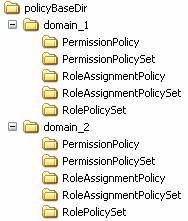
figure 5 Directory structure
for RBAC XACML policies
4.3.1.1 Domains
The main idea behind the domain concept is
to provide a measure to differentiate role sets for different application or
policy domain specifics. So, e.g. a server hosting different providers or
databases may start a PEP instance for each provider or database hosted. Configuring
the PEP to use the policies defined within a domain for each provider eases the
maintenance of the policies. Nevertheless, you must specify at least one
domain, even if you are serving just one domain.
4.3.1.2 Identifier
The XACML standard requires that every type
of policy element must have an identifier [MOS05]. Furthermore, it requires
that no two policies have the same identifier, which may be achieved following
a predefined URN or URI scheme. Therefore, we extended this requirement to
XACML Rule elements also, resulting in an identical naming convention for all
relevant policy elements. Thus, we defined a scheme for our RBAC policies and
rules as follows:
·
urn:<domain_label>:<policy_type>:<policy_label>.
The accepted values for <policy_type> are
· RoleAssignmentPolicySet
· RoleAssignmentPolicy
· RolePolicySet
· PermissionPolicySet
· PermissionPolicy.
The values for <policy_label>
and <domain_label> describe the name of the policy or denote the
name of the domain, which the policy element belongs to.
The current implementation maps this naming
scheme onto the file system. For that, all ":" of the naming scheme
are replaced by the path separator of the underlying operating system. The
policy file name is built concatenating the value of <policy_label>
and the XML file suffix ".xml". The result is a relative file path
unique within the system's policy base directory.
Example:
The identifier
"urn:domain_1:RolePolicySet:role_1" is mapped to the relative file
path "domain_1/RolePolicySet/role_1".
This way, all policy types can be
unambiguously stored and retrieved from the file system. Note, that because
domain and policy labels must be representable in the file system, the syntax
for labels is restricted to the Namespace Identifier Syntax as defined in RFC
2141 [=14 - Moats 1997 URN Syntax...=].
4.3.1.3 RoleAssignmentPolicy(Set)
As defined in [A05], a RoleAssignmentPolicy
or RoleAssignmentPolicySet determines which users are enabled to which roles
and under which conditions. These policies are used be the Role Enablement Authority
to determine whether a subject - identified by an X509 certificate - has a
particular role attribute value. The RoleManager organises role assignments as
follows:
The RoleAssignmentPolicySet includes
RoleAssignmentPolicies using PolicyReferences to support combining role
assignments from different sub roles or the construction of hierarchical
role sets. Currently, the RoleManager only supports referencing one
RoleAssignmentPolicy per RoleAssignmentPolicySet. A RoleAssignmentPolicy
determines the real user to role assignments according to [A05]. The
assignments consist of multiple subjects, identified by its X.500 Distinguished
Name, a role_value resource storing the role label and the predefined action
enableRole. See the next table for detailed XACML values and data types.
|
Element |
Value |
XACML data type |
|
Subject |
X500 Distinguished Name |
urn:oasis:names:tc:xacml:1.0:data-type: |
|
Resource |
<domain_label>:role_value: |
http://www.w3.org/2001/XMLSchema#anyURI |
|
Action |
urn:oasis:names:tc:xacml:2.0: |
http://www.w3.org/2001/XMLSchema#anyURI |
The RoleManager supports the following XACML
PolicyCombiningAlgorithms for a RoleAssignmentPolicySet:
·
urn:oasis:names:tc:xacml:1.0:policy-combining-
algorithm:permit-overrides
The RoleManager supports the following XACML
RuleCombiningAlgorithms for a RoleAssignmentPolicy:
·
urn:oasis:names:tc:xacml:1.0:rule-combining-
algorithm:permit-overrides
4.3.1.4 RolePolicySet
A RolePolicySet associates users with
particular role value attributes to a PermissionPolicySet. This
PermissionPolicySet contains the permissions associated with the given role.
According to [A05], each RolePolicySet references at most one
corresponding PermissionPolicySet. The XACML target limits the applicability of
the RolePolicySet to subjects with the given role value attribute.
The RoleManager supports the following XACML
PolicyCombiningAlgorithms for a RolePolicySet:
·
urn:oasis:names:tc:xacml:1.0:rule-combining-
algorithm:permit-overrides
4.3.1.5 PermissionPolicySet
A PermissionPolicySet references the
PermissionPolicies describing the resources and actions that subjects with a
particular role value attribute are permitted to access. [A05] also specifies
the inheritance of PermissionPolicySets as junior roles. Unfortunately, this is
currently not supported by the RoleManager but may be added in future versions.
The RoleManager supports the following XACML
PolicyCombiningAlgorithms for PermissionPolicySets:
·
urn:oasis:names:tc:xacml:1.0:policy-
combining- algorithm:permit-overrides
·
urn:oasis:names:tc:xacml:1.0:policy-combining-algorithm:deny-
overrides
4.3.1.6 PermissionPolicy
A PermissionPolicy describes the resources
and actions that subjects are permitted to access. These Permissions are
determined by Rules contained in a PermissionPolicy. [A05] also specifies the
addition of further conditions to the application of such permissions.
The RoleManager only supports the following
RuleCombiningAlgorithms for a PermissionPolicy:
·
urn:oasis:names:tc:xacml:1.0:rule-combining-
algorithm:permit-overrides
·
urn:oasis:names:tc:xacml:1.0:rule-combining-algorithm:deny-overrides
4.3.2 Commands
The RoleManager offers a command line
interface to the user providing several commands supporting the most important
role management task. Currently, the interface implements the commands add,
remove, list and help. Each command may be parameterised
by several options. The following sections explain the available commands in
detail.
4.3.2.1 Add (-a, --add)
This command adds or updates policy elements. If necessary, it creates any missing policy elements needed to process the command. The add command may be used to
· add users to a role
·
add permission policies to a
role
· add permissions to a permission policy
·
add conditions to a permission
policy
4.3.2.1.1 Add users to a role
When adding users to a role, this means that an Assignment will be added to a RoleAssignmentPolicy (Set). Currently, users are represented by their X509 certificates. Thus, to process the command, the following arguments are needed:
|
Option |
Description |
|
-D |
domain label |
|
-R |
role label |
|
-U |
list of X.509 certificate file paths
of users to add |
If the domain or the
RoleAssignmentPolicySet and RoleAssignmentPolicy relying on the given role are
inexistent, they are created.
4.3.2.1.1.1
Examples
The following command adds the user with
the X509Certificate stored in ./CA/UserCA/user_1.crt to the role users
of the domain domain
-a -D domain -R users -U
./CA/UserCA/user_1.crt
The following command adds the users with
the X509Certificates stored in ./CA/UserCA/user_1.crt and ./CA/UserCA/user_2.crt
to the role users of the domain domain.
-a -D domain -R users -U
./CA/UserCA/user_1.crt ./CA/UserCA/user_2.crt
4.3.2.1.2
Add PermissionPolicies to a
role
When adding PermissionPolicies to a role,
this means that a PermissionPolicy will be added to a PermissionPolicySet. Thus,
a PolicyReference to the PermissionPolicy will be added to the
PermissionPolicySet for the given role The command requires the following
arguments:
|
Option |
Description |
|
-D |
domain label |
|
-R |
role label |
|
-P |
list of PermissionPolicies to add |
If the domain or the PermissionPolicySet
and RolePolicySet or PermissionPolicy relying on the given role are inexistent,
they are created.
4.3.2.1.2.1
Examples:
The following command adds the
PermissionPolicy userperm_1 to the role users of the domain domain
-a -D domain -R users -P userperm_1
The following command adds the
PermissionPolicies userperm_1 and userperm_2 to the role users
of the domain domain.
-a -D domain -R users -P userperm_1
userperm_2
4.3.2.1.3 Add Permissions to a PermissionPolicy
When adding permissions to a PermissionPolicy, this means that the Rules representing the Permission will be added to the given PermissionPolicy. The command requires the following arguments:
|
Option |
Description |
|
-D |
domain label |
|
-P |
PermissionPolicy to update |
|
-p |
permission label to add |
|
-d |
Flag setting the permission effect to
deny (otherwise permit) |
|
-y |
list of resources to be added to the
permission |
|
-z |
list of actions to be added to the
permission |
If the domain, PermissionPolicy or Permission
to be updated is inexistent, it was created.
The syntax scheme to define target
resources or actions of permissions describes clause 4.3.4.
4.3.2.1.3.1
Examples:
The following command adds the Permission perm_1
which effects to permit to the PermissionPolicy userperm_1 of the
domain domain
-a -D domain -P userperm_1 -p perm_1
The following command adds the Permission perm_1
which effects to deny to the PermissionPolicy userperm_1 of the
domain domain
-a -D domain -P userperm_1 -p perm_1 -d
The following command adds the Permission perm_1
which effects to permit to the PermissionPolicy userperm_1 of the
domain domain and defines that the action must be equal to the string
"action_1".
-a -D domain -P userperm_1 -p perm_1 -z
string-equal[action_1]
The following command adds the Permission perm_1
which effects to deny to the PermissionPolicy userperm_1 of the
domain domain and defines that the action must be equal to the string
"action_1" and matches any string resource containing the
string "resource"
-a -D domain -P userperm_1 -p perm_1 -d -y string-match[resource] -z string-equal[action_1]
4.3.2.1.4
Add Conditions to Permissions
When adding a Condition to Permissions, this means that the Rules representing the Permission are extended by the given condition. The command requires the following arguments:
|
Option |
Description |
|
-D |
domain label |
|
-P |
PermissionPolicy to update |
|
-p |
permission label to update |
|
-C |
Condition to be added to the
permission |
If the domain, PermissionPolicy, Permission
or Condition to be updated is inexistent, it is created.
The syntax scheme to define conditions describes
clause 4.3.5.
4.3.2.1.4.1
Examples:
The following command adds the Condition integer-less-than[env[limit],10] to the permission perm_1, which effects to permit the
request action of the permission perm_1 only when the environment
attribute limit evals to an integer value less than 10.
-a -D domain -P userperm1 -p permit_1 -C integer-less-than[env[limit],10]
4.3.2.2 Remove (-r, --remove)
This command removes policy elements. The remove command may be used to
· remove users from a role
·
remove permission policies from
a role
· remove permissions from a permission policy
· remove conditions from a permission
· remove roles completely
·
remove domains completely
4.3.2.2.1 Remove users from a role
When removing users from a role, this means
that an Assignment will be removed from a RoleAssignmentPolicy(Set). Currently,
users are represented by their X509 certificate. Thus, to process the command,
the following arguments are needed:
|
Option |
Description |
|
-D |
domain label |
|
-R |
role label |
|
-U |
list of X.509 certificate file paths
of users to remove |
This command removes the corresponding
Assignments from the given RoleAssignmentPolicy. If there are no users left,
the RoleAssignmentPolicy will not be deleted!
4.3.2.2.1.1
Examples:
The following command removes the user with
the X509Certificate stored in ./CA/UserCA/user_1.crt from the role users
of the domain domain
-r -D domain -R users -U
./CA/UserCA/user_1.crt
The following command removes the users
with the X509Certificates stored in ./CA/UserCA/user_1.crt .and ./CA/UserCA/user_2.crt
from the role users of the domain domain
-r -D domain -R users -U
./CA/UserCA/user_1.crt ./CA/UserCA/user_2.crt
4.3.2.2.2 Remove PermissionPolicies from a role
When removing PermissionPolicies from a role, this means that a PermissionPolicy will be removed from a PermissionPolicySet. For that, the PolicyReference to the PermissionPolicy will be removed from the PermissionPolicySet for the given role. The command requires the following arguments:
|
Option |
Description |
|
-D |
domain label |
|
-R |
role label |
|
-P |
list of PermissionPolicies to remove |
If there are no PolicyReferences left, the PermissionPolicySet
will not be deleted!
4.3.2.2.2.1
Examples:
The following command removes the
PermissionPolicy userperm_1 from the role users of the domain domain.
-r -D domain -R users -P userperm_1
The following command removes the
PermissionPolicies userperm_1 and userperm_2 to the role users
of the domain domain.
-r -D domain -R users -P userperm_1
userperm_2
4.3.2.2.3 Remove Permissions from a PermissionPolicy
When removing permissions from a PermissionPolicy, this means that the Rules representing the Permission will be removed from the given PermissionPolicy. Furthermore, actions or resources can be removed from the Permission. The command requires the following arguments:
|
Option |
Description |
|
-D |
domain label |
|
-P |
PermissionPolicy to update |
|
-p |
Permission to remove |
|
-d |
Flag setting the Permission’s effect
to deny (otherwise permit) |
|
-y |
list of resources to remove from the Permission |
|
-z |
list of actions to remove from the Permission |
For the syntax scheme to define resources
or actions for permission see clause 4.3.4.
4.3.2.2.3.1
Examples:
The following command removes the
Permission perm_1 from the PermissionPolicy userperm_1 of the
domain domain.
-r -D domain -P userperm_1 -p perm_1
The following command removes the action
equalling the string "action_1" from the Permission perm_1
of the PermissionPolicy userperm_1 of the domain domain.
-r -D domain -P userperm_1 -p perm_1 -z
string-equal[action_1]
The following command removes the action equalling
the string "action_1" and the resource matching the string
"resource" from the Permission perm_1 of the
PermissionPolicy userperm_1 of the domain domain.
-r -D domain -P userperm_1 -p perm_1 -y
string-match[resource] -z string-equal[action_1]
4.3.2.2.4 Remove Conditions from a Permission
When removing a Condition to Permissions, this means that the Rules representing the Permission are freed from the given condition. The command requires the following arguments:
|
Option |
Description |
|
-D |
domain label |
|
-P |
PermissionPolicy to update |
|
-p |
permission label to update |
|
-C |
Condition to be removed
from the permission |
The syntax scheme to define
conditions describes clause 4.3.5.
4.3.2.2.4.1
Examples:
The following command removes
the Condition integer-less-than[env[limit],10] from the permission perm_1.
-r -D domain -P userperm1 -p permit_1 -C integer-less-than[env[limit],10]
4.3.2.2.5 Remove roles completely
This command removes the RoleAssignmentPolicySet, RoleAssignmentPolicy, RolePolicySet and PermissionPolicySet of the given role. All the related files are deleted from the file system. The command requires the following arguments:
|
Option |
Description |
|
-D |
domain label |
|
-R |
List of roles to remove |
4.3.2.2.5.1
Example:
The following command removes the role users
of the domain domain completely.
-r -D domain -R users
4.3.2.2.6 Remove domains completely
This command removes the given domain completely from the file system. All corresponding policy files are lost. The command requires the following arguments:
|
Option |
Description |
|
-D |
domain label |
4.3.2.2.6.1
Example:
The following command removes the domain domain.
-r -D domain
4.3.2.3 List (-l, --list)
The list command prints defined Roles,
Users and Permissions to the screen.
4.3.2.3.1.1
Examples
The following command lists all available domains,
roles, users and Permissions.
-l
The following command lists all available roles,
users and Permissions labels of the domain domain to the
screen.
-l -D domain
The following command lists all available role
labels of the domain domain to the screen.
-l -D domain -R
The following command lists all available
PermissionPolicy labels of the domain domain to the screen.
-l -D domain -P
The following command lists all available Permission
labels of the PermissionPolicy userperm_1 within the domain domain
to the screen:
-l -D domain -P userperm_1 -p
4.3.2.4 Help (-h, --help)
The help command prints a short command
description of the RoleManager to the screen.
4.3.2.4.1.1
Example:
The following command prints the command
description to the screen:
-h
4.3.3 Options
The commands offered by RoleManager need several parameters to operate. These parameters are given to the RoleManager’s command line using options. See the following table for supported options.
|
Name |
Long Name |
Arguments |
Commands |
|
-d |
--Deny |
|
add permissions, |
|
-D |
--Domain |
<label list> |
all except help |
|
-U |
--User |
<cert file list> |
add/remove users |
|
-z |
--targetAction |
<datatype-matchfunc[value]> |
add/remove permissions |
|
-y |
--targetResource |
<datatype-matchfunc[value]> |
add/remove permissions |
|
-R |
--Role |
<label list> |
all except help |
|
-P |
--PermissionPolicy |
<label list> |
add/remove permissions, add/remove
permission policies |
|
-p |
--Permission |
<label list> |
add/remove permissions, add/remove
permission policies |
|
-C |
--Condition |
<label list> |
add/remove conditions |
|
|
--policyBaseDir |
<dir path> |
all except help |
The following sections explain the
available options in detail.
4.3.3.1
Deny (-d, --Deny)
Sets Permission’s effect to deny or
sets the combining algorithm of a PermissionPolicy or PermissionPolicySet to urn:oasis:names:tc:xacml:1.0:policy-combining-algorithm:deny-
overrides.
4.3.3.2 Domain (-D, --Domain <label list>)
This option specifies at least one domain
name for the given command. Multiple domain parameters are supported for the
command remove domains completely only (see clause 4.3.2.2.6). This option overwrites any default setting from the
configuration file (see clause 4.1).
4.3.3.3 User (-U,--User <cert file list>)
This option specifies at least one path to
an X.509 certificate file.
4.3.3.4 targetAction (-z,--targetAction <datatype- matchfunc[value]>)
This option specifies at least one XACML
action target of Permission. The syntax scheme of the arguments describes clause
4.3.4.
4.3.3.5 targetResource (-y,--targetResource <datatype-
matchfunc[value]>)
4.3.3.6
Role (-R,--Role <label list>)
This option specifies at least one role
value for the given command. Multiple role value parameters are supported for
the command remove roles completely only (see clause 4.3.2.2.4).
4.3.3.7 PermissionPolicy (-P,--PermissionPolicy <label list>)
This option specifies at least one
PermissionPolicy for the given command. When adding or removing permissions (see
clauses 4.3.2.1.3, 4.3.2.2.3) only the first label from the list is evaluated.
4.3.3.8 -p,--Permission <list of labels>
This option specifies at least one
Permission for the given command. When adding or removing target actions or
resources (see clauses 4.3.2.1.3, 4.3.2.2.3) only the first label from the list is evaluated.
4.3.3.9 -C,--Condition <list of labels>
This option specifies at
least one Condition for the given command.
4.3.3.10
--policyBaseDir
This option specifies the policy base
directory for the given command. This option overwrites any default setting
from the configuration file (see clause 4.1).
Command: all except for help.
4.3.4 Target syntax scheme description
The syntax scheme to define resources or
actions for permission is defined as follows:
· datatype-matchfunc[value]
Currently the following data types are supported:
|
Data Type |
Description |
|
string |
declares the value as a string |
|
Anyuri |
declares the value as a URI |
|
x500Name |
declares the value as a X500Principal |
The datatype may be combined with the
following match functions:
|
Match Function |
Description |
|
Equal |
equals the value |
|
Match |
match the value as regular expression
(string and x500Name) |
4.3.4.1 Example
To match the string “pattern” within Permission targets uses the following target declaration:
· String-match[pattern]
4.3.5 Condition syntax scheme description
· datatype-matchfunc[attr_type(value1[, value2, ...])]
It introduces an attribute type selector permitting to select the scope of the function (sub for subject, res for ressource, act for action and env for environment) or to evaluate attribute values repectively. Currently, only the latter is supported within the PEP’s implementation, especially to support the evaluation and comparison of environment attributes within BioCASE protocol request.
It supports multiple function values and values may be represented by function results also. This becames necessary to support comparison functionality of environment attributes in permission policies
Currently, it should support all comparison functions defined in the XACML standard [MOS05] and supported by Sun’s XACML Implementation [SUN04a].
On
user request, this scheme may be extended in the future, to replace the current
target syntax scheme for actions and resources. This would be done adding an
implementation of the sub, res and act scope selectors and abandons the current
–z and –y parameters to define actions and resources using the RoleManager.
4.3.5.1 Example
To evaluate the environment attribute limit of the responseFormat element “limit” and to verify, if it is less than 10, use the following declaration:
·
integer-less-than[env[limit],10]
4.4 Policy Enforcement Point
The task of the PEP is to await
BioCASE-requests, evaluate the access rights related to the requesting entity
and process the request according to these access rights. The BioCASE-requests
are embedded within the Https-protocol, which uses the SSL authentication
protocol to determine the authenticity of the requesting client. For that, each
client must own an X509-certificate.
The Policy Enforcement Point (PEP)
encapsulates two components:
· Role Enablement Authority (REA)
· Policy Decision Point (PDP).
The REA evaluates the roles assigned to an authenticated client. The evaluation process founds on the Role Enablement Policies defined for the REA's security domain. There are two predefined roles specified for the PEP.
· guest
· trustedClient
If the client’s authenticity can not be verified, then the REA assigns the predefined guest role to this request (see clause 2.3.5).
If the provider especially trusts in the
reliabity and authentication mechanisms of a client, e.g. a web portal or a
special client application, then he may assign this client the role trustedClient.
This role allows the client to pass the X.509 certificate of the trusted client
to the PEP using the special Http request parameter clientCert.
Parameterised with the evaluated roles for the request, the PDP decides on the further processing of the request. Requests may be blocked completely or redirected to the protected BioCASE-provider.
BioCASE-responses returned from the
provider are filtered according to the XACML policies defined using the
RoleManager. Within this filtering process, parts of the XML-structure of the
provider's response content may be eliminated in the final response delivered
to the PEP (see clause 4.5). Finally, the PEP embeds the remaining BioCASE-
response in a Https-response and returns the latter to the requesting client.
The configuration details for the PEP
describes clause 4.1.2), The PEP may be started using the distribution’s
bash-script PEP or running the Java class nbi.xmlsec.PEP. The
command has no parameters.
4.5 BioCASE Integration
The current implementation of the PEP (PDP) supports the BioCASE protocol version 1.3 [TSL+04]=17 - BioCASE Se... 2005 The BioCASE unit-lev...=]. The integration of the BioCASE-protocol within the XACML architecture needed some adaptation efforts. Namely, the BioCASE protocol specifies three commands (capabilities, scan and search), each requiring a separate processing. A different processing is required for BioCASE request and responses also. Therefore, some rules must be respected when defining policies using the RoleManager. Furthermore, some commitments concerning the handling of some protocol operators must have been taken. Both are subject of the next sections.
4.5.1
Policy Definition Rules
The BioCASE protocol provides three request
methods (capabilities, scan and search) and each requires special processing
regarding the PDP's policy evaluation. Additionally, because requests can only
be blocked and responses can only be filtered, the PDP uses two processing
chains for each method - one for requests and one for responses.
4.5.1.1 Request processing
Due to the fact that methods are the active
components within a BioCASE-request, the method names are considered as
actions, whereas the path used within the filter element of the search request and
the value of the concept element of the scan request are interpreted as
resources. Regarding the capabilities method, requests can only be permitted or
denied based on the request method. Thus, for the evaluation of requests a
Permission’s action target must be defined using the RoleManager according to
the following pattern:
|
string-equal[<method>-request] |
where as <method> may be
replaced by one of the strings "capabilities", "scan" or
"search" |
Example:
|
string-equal[search-request] |
matches a search request |
Furthermore, several paths or concepts can
be added as resources to a permission for scan or search requests. During the
request evaluation process, the PDP evaluates the defined PermissionPolicies by
looking up for matches between the actual request and the PermissionPolicies
defined with the RoleManager.
As stated above, if the evaluated request
type is scan, than the PDP looks for matches within the value of the
concept element of a scan request.
If the request type equals to search,
then the path attribute of the filter sub elements of the search request is
evaluated by the PDP.
In both cases, the PDP tries to match
string values represented by the concatenation of the request format and the
path or concept value of the request. So, if a scan or search request
permission for the ABCD resource /DataSets/DataSet/Units/Unit/Identifications/Identification/TaxonIdentified/NameAuthorYearString shall be defined, then the following string must be added to the
target resources:
http://www.tdwg.org/schemas/abcd/1.2/DataSets/DataSet/Units/Unit/Identifications/Identification/TaxonIdentified/NameAuthorYearString
Currently, you can define the match functions string-equal and string-match only. Future versions may support XPath expressions also.
Example:
|
string-equal[http://www.tdwg.org/schemas/abcd/1.2
/DataSets/DataSet/Units/Unit/Identifications/Identification/TaxonIdentified/NameAuthorYearString] |
matches the given ABCD concept if
equal |
|
string-match[http://www.tdwg.org/schemas/abcd/1.2
/DataSets/DataSet/Units/Unit/Identifications/Identification] |
matches all ABCD sub concepts of
Identification (regular expression) |
Furthermore, using conditions (see clause 4.3.2.1.4) the evaluation of the following environment attributes is implemented to be used within BioCASE protocol requests:
|
Attribute |
Description |
|
source |
The source attribute of the header
element as StringAttribute |
|
requestFormat |
The requestFormat of Scan or Search
requests as AnyUriAttribute |
|
responseFormat |
The responseFormat of search
requests as AnyUriAttribute |
|
start |
The start attribute of the
responseFormat element of search requests as IntegerAttribute |
|
limit |
The limit attribute of the
responseFormat element of search requests as IntegerAttribute |
|
count |
The count attribute of the
responseFormat element as BooleanAttribute |
Example:
|
integer-less-than[env[limit],10] |
Evaluates the environment attribute
limit of the responseFormat element limit and compares it to the
integer value 10 |
4.5.1.2 Response processing
Analogous to the processing of
BioCASE-requests, method names are considered as actions within
BioCASE-responses also. But this time, the pattern to be used for the
definition of the action target of Permissions should be defined as follows:
|
string-equal[<method>-response] |
where as <method> may be
replaced by one of the strings "capabilities", "scan", "search"
or “sign”. |
Example:
|
string-equal[search-response] |
matches a search response |
When the PDP evaluates the
BioCASE-responses, it considers the value of the content element as
XML-document, the namespace of this document and the response format from the
related BioCASE-request. First, the PDP checks the access permissions for every
sub element and attribute of this XML-document. If permission is denied for an
element of the response's content document, access is also denied for any
attributes and sub elements of this element. All elements stated above will be
eliminated from the final response to the requesting client. If permission is
denied for an element's attribute, only this attribute will be eliminated from
the final response to the client. Therefore, the PDP also verifies for each sub
element and attribute, if the namespace of the XML-document matches the
response format requested. Thus, unlike the description of request processing
above, the permissions for scan or search responses must define resource target
defined using the RoleManager applicating the following rules:
If search or sign response
permission for the ABCD resource /DataSets/DataSet/Units/Unit/Identifications/Identification/TaxonIdentified/NameAuthorYearString
shall be defined, then the following string
must be added to the target resources:
http://www.tdwg.org/schemas/abcd/1.2/DataSets/DataSet/Units/Unit/Identifications/Identification/TaxonIdentified/NameAuthorYearString
If scan or capabilities response permission shall be defined, then the response format equals the namespace of the BioCASE- protocol:
http://www.biocase.org/schemas/protocol/1.3
To match the values of a scan response, the
following string must be stated in the match function:
http://www.biocase.org/schemas/protocol/1.3/scan/value
Attributes to be matched shall be given by
appending "@" and the attribute name to the related element path,
such as
http://www.tdwg.org/schemas/abcd/1.2/DataSets/DataSet/Units/Unit/Identifications/Identification/TaxonIdentified/NameAuthorYearString@attribute
Currently, you can define the match functions string-equal and string-match only. Future versions may support XPath expressions also.
Examples:
|
string-equal[http://www.tdwg.org/schemas/abcd/1.2 |
matches the given ABCD element and all
sub elements if equal. |
|
string-match[http://www.tdwg.org/schemas/abcd/1.2 |
matches all ABCD Identification sub
concepts within the response document (regular expression) |
4.5.1.3 Response signing
Response signing is a special part of the response processing. The response signing process follows the handling of permitted content document elements in the response processing. The signing process covers element processing only. Attributes can not be subject of the signing process.
The remaining permitted elements and all of its subelements will be signed, if there is a permission action target sign-response defined together with a resource target matching the related element. The matching process corresponds to the matching process for the action target search-response described above. For that, each matching element was appended to a list of content document elements to be signed.
At the end of the response
processing, the content document will be signed if the list of signable
elements holds at least one element. The signing process is executed along the
XML-Signature standard [ERS02]. The content document will be signed in detached
mode, i.e. the signature element is appended as sibling of the content document
within the BioCASE response. Each element paths in the list of signable
elements is included as reference in the generated XML-Signature.
4.5.1.4 Combining algorithms deny-overrides vs. permit-overrides
Using the RoleManager’s option –d (see clause 4.3.3.1), the combining algorithm of an XACML PermissionPolicy can be determined. The combining algorithm deny-overrides determines, if only one Permission within a PermissionPolicy evaluates to deny, then the result of the whole evaluation is deny. Vice versa, the combining algorithm permit-overrides determines, if only one Permission within a PermissionPolicy evaluates to permit, then the result of the whole evaluation is permit.
Note, that the combining algorithm possibly
influences the intended effect of the permission evaluation process. Let's
demonstrate the effect on the following simple example.
Say, the following two resources are
defined for a search response.
|
string-match[http://www.tdwg.org/schemas/abcd/1.2 |
permit all elements of an ABCD
document |
|
string-
equal[http://www.tdwg.org/schemas/abcd/1.2 |
deny all ABCD elements below
/DataSets/DataSet/Units/Unit/Identifications |
If the combining algorithm is defined to permit-overrides,
then the PDP would permit a request on the resource
http://www.tdwg.org/schemas/abcd/1.2/DataSets/DataSet/Units/Unit/Identifications/Identification/TaxonIdentified/Name.
But if the combining algorithm is defined deny-overrides,
the same request would be evaluated by the PEP to deny.
Nevertheless, the availability of both algorithms provides to determine access policies as "black lists" or "white list" and may be helpful to save unnecessary typing efforts when defining permission policies.
4.6 Client API
The client API manages communication with
the Policy Enforcement Point (PEP) of a BioCASE provider. For that, the Java
class nbi.xmlsec.PEPClient provides methods to send and receive BioCASE
request and responses from PEPs. Furthermore, these methods hide the complexity
of security related features like client authentication and signature
verification for its users. Additionally, the package nbi.xmlsec.biocase.protocol
provides classes to build and evaluate BioCASE requests and responses to be
used in the PEPClient class.
To use client authentication and signature verification easily, the PEPClient should be configured as described in clause 4.6.1. Client authentication is needed if you send requests to the PEP. Depending on the client identity, the PEP assigns role based access rights to the connecting client defined in its policies.
For certain roles, the PEP may be configured to sign the content document within its BioCASE response using the XML-Signature standard. The PEPClient automatically recognises signed responses and verifies the signatures and certificate chains using the default Java built-in standard PKIX[IET05]. The result will be reported in the Diagnostics parts of the BioCASE response. Therefore, the special value “SECURITY” was introduced, signaling security related information in the attribute code of the Diagnostic elements in the BioCASE response.
The client API may also be used in web
portals or web interface application servers, which authenticate client on
their own. For that, the PEP may assign a specific role, called “trustedClient”,
to some trustworthy clients. This role allows these clients, after successfully
authenticating themselves to the PEP, to pass the X.509 certificate of their
authenticated clients to the PEP. Then, the PEP handles the related request, as
if it would come from the client identified within the transmitted certificate.
The send method of the PEPClient class, provides an extra parameter to
enter the trusted client mode and pass the related client certificate to the
PEP. For that, the send method encodes the certifcate with a base64URLEncoder
and transmits the certificate to the PEP adding the parameter clientCert
of the relating Http request.
In the following sections, the configuration of the PEPClient and a small code example illustrating the usage of the client API is presented.
4.6.1 Configuration
The configuration of the PEPClient is
analogous to the general configuration of the Role Manager and PEP described in
clause 4.1. The configuration consists of the file
"config.xml" specifying the configuration objects to load. We use an
XML based configuration object, which is stored in an XML file to be configured
within the attribute "fileName" of the element "xml" in the
config.xml.
<?xml version="1.0"
encoding="ISO-8859-1" ?>
<configuration>
<xml fileName="PEPClientconfig.xml"/>
</configuration>
Currently, there is not DTD or XML schema
to describe the format, neither from the Commons Configuration project, nor
from us. So, the relevant parameters will be explained in the next sections.
The root element is ignored, so the configuration of a component starts with the element PEPClient, which currently has no attributes.
The subelement PEP configures the URL of the PEP to be used. The usage of SSL authentication will automatically be recognised, if the protocol https was configured.
|
/PEPClient/PEP |
|
|
Attribute |
Function |
|
url |
URL of the PEP to communicate with. |
Next, the keystore has to be defined, where the PEPClient retrieves the private key and X.509 certificate of the client. The generation of these keys describes clause 4.2. In the configuration, you have to state the path to the keystore file, the type of the keystore (usually PKCS12) and the password to open the keystore.
Note: For security reason, make sure that nobody except you can read this configuration file.
|
/PEPClient/KeyStore |
|
|
Attribute |
Function |
|
file |
Path to the keystore file |
|
type |
Type of the keystore (e.g. PKCS12,
JKS) |
|
password |
Password of the keystore |
A keystore may contain multiple key pairs. So, Key element specifies the alias name of the key within the keystore and the password of the key.
|
/PEPClient/Key |
|
|
Attribute |
Function |
|
alias |
Alias name of the key in the keystore |
|
password |
Password of the key |
Finally, to verify the authenticity of the PEP’s certificate and to verify the signature of the possibly signed content document of the PEP’s BioCASE response, the truststore holds a list of certificates from trusted certification authorities.
|
/PEPClient/TrustStore |
|
|
Attribute |
Function |
|
file |
Path to the keystore file |
|
password |
Password of the keystore |
The following lines present an example PEPClient configuration file:
<Configuration>
<PEPClient>
<PEP
url="https://localhost" />
<KeyStore file="CA/UserCA/client.p12"
type="PKCS12" password="client" />
<Key alias="BioCASE Client 2048 Bit
Zertifikat" password="client" />
<TrustStore file="./jssecacerts"
password="provider" />
</PEPClient>
</Configuration>
4.6.2 Code Example
The following lines present a commented
code example illustrating the usage of the client API. The example describes
the creation, sending and receiving of a BioCASE search request. For a detailed
API description, please see the JavaDoc documentation of the distribution.
First, we create a request and a header for the BioCASE protocol version 1.3.
Request request = new Request(ProtocolFilter.PROT_URI_13);
Header requestHeader = new Header(ProtocolFilter.PROT_URI_13);
We want to send a search request, so let’s set the header’s Type and assign the header to the request.
requestHeader.setType("search");
request.setHeader(requestHeader);
Now we create specify the operation type (also for BioCASE V1.3)
SearchOperationType requestSearchOp = new SearchOperationType(ProtocolFilter.PROT_URI_13);
We request an ABCD document V1.2.
requestSearchOp.setRequestFormat("http://www.tdwg.org/schemas/abcd/1.2");
requestSearchOp.setResponseFormat("http://www.tdwg.org/schemas/abcd/1.2");
We set the responseFormat attributes start, limit and count..
requestSearchOp.setResponseFormatStart(new Integer(0));
requestSearchOp.setResponseFormatLimit(new Integer(10));
requestSearchOp.setCount(Boolean.FALSE);
We want to search for all database
entries for Luzula acerifolium subsp. Arbiales in Germany. So, we filter the
results of the comparativ operator like for the CountryName and the
comparativ operator equals for the NameYearAuthorString element using
the logical operator and.
LOP andOp = new LOP(ProtocolFilter.PROT_URI_13, LOPFilter.LN_AND);
COP likeOp = new COP(ProtocolFilter.PROT_URI_13, COPFilter.LN_LIKE);
likeOp.setPath("/DataSets/DataSet/Units/Unit/Gathering/GatheringSite/Country/CountryName");
likeOp.setValue("Ger*");
COP equalsOp = new COP(ProtocolFilter.PROT_URI_13, COPFilter.LN_EQUALS);
equalsOp.setPath("/DataSets/DataSet/Units/Unit/Identifications/Identification/TaxonIdentified/NameAuthorYearString");
equalsOp.setValue("Luzula acerifolium subsp. arbiales");
andOp.addOperator(likeOp);
andOp.addOperator(equalsOp);
Set filter of the Operation type and assign the operation type to the request.
requestSearchOp.setFilter(andOp);
request.setOpType(requestSearchOp);
Now, set up the PEPClient using the configuration file.
ConfigurationFactory factory = new ConfigurationFactory("config.xml");
Configuration config = factory.getConfiguration();
PEPClient pepclt = new PEPClient(config);
Send the request in normal mode
pepclt.send(request, wrapperDatabase, true,null);
Send the request in trustedClient mode
X509 Certificate cert = getClientCertificate()
pepclt.send(request, wrapperDatabase, true, cert);
Get the response
Response response = pepclt.getResponse();
To read the client certificate from a keystore, the following function may be helpful.
X509Certificate
getClientCertificate(String clientKeyStore, String type, String passwd, String
keyAlias)
{
X509Certificate result = null;
try {
KeyStore keystore = KeyStore.getInstance(type);
keystore.load(new FileInputStream(clientKeyStore),
passwd.toCharArray());
result = (X509Certificate) keystore.getCertificate(keyAlias);
} catch (Exception e) {
logger.fatal(e.getMessage());
}
return result;
}
5 Installation
The following section provides a small guide through the installation process of the software distribution and some third party products required to run the PEP and RoleManager. The guide includes the following aspects:
· Web Browser X.509 Certificate Installation
· OpenSSL
· BioCASE provider
· Access control software distribution
Finally, the example scenario also included
in the software distribution is described. It may be helpful testing the
correct installation of all required software components.
5.1 Browser Certificate Installation
To install the web browser, please refer to the installation instructions of your favourite browser. As an example, the installation of the X.509 certificates for clients is described within the following sections for the popular web browsers
· Mozilla Firefox
·
Microsoft Internet Explorer
5.1.1
Firefox
To install the user certificates, open
FireFox's certificate manager following the menu entry Tools/Options/Advanced/Certificates
and pushing the button "Manage Certificates". Click on the tab
"Your Certificates" and then on the button "Import".
Now, choose the certificates files to install. Example user certificates for
the users nobody, client and expert can be found in the
unzipped distribution subdirectory Keys/UserCA. The have the suffix
".p12" and are PKCS#12-files. The passwords for this example
files equals to their user names(e.g. expert).
To install the certificate of the RootCA,
import the file Keys/RootCA/RootCA.crt from the distribution under the
tab "Authorities". To install the certificate of the ServerCA,
use the file Keys/ServerCA/ServerCA.crt under the tab "Web Sites".
5.1.2
Internet Explorer
To install the user certificates, open
Internet Explorer's Certificates dialog following the menu entry Tools/Internet
Option and pushing the button "Certificates". Next, click
on the tab "Personal" and then the button "Import".
Now, choose the certificates files to install. Example user certificates for
the users nobody, client and expert can be found in the
unzipped distribution subdirectory Keys/UserCA. The have the suffix
".p12" and are PKCS#12-files. The passwords for this example
files equals to their user names(e.g. expert).
To install the certificate of the RootCA,
import the file Keys/RootCA/RootCA.crt from the distribution under the
tab "Trusted Root Certification Authorities". To install the
certificate of the ServerCA, use the file Keys/ServerCA/ServerCA.crt
under the tab "Intermediate Certification Authorities".
5.2
OpenSSL
For OpenSSL installation instructions
please refer to [THE05b].
To build up a PKI and generate keys and
certificates for client and servers refer to clause 4.2.
5.3
BioCASE Provider
The BioCASE provider software version 2.31
should be available from the BioCASE Secretariat [BIO05]. A detailed
installation instruction is provided on [ASA+02].
5.4 Software distribution
To install the software distribution, unzip
the content of the zip-file in a suitable system directory. Ensure that no
unauthorized users have access to that directory.
The distribution contains an Ant-file
(build.xml). The second line of the build.xml defines the property "dir.jdk".
Please modify the value of this property, so that it points to the directory,
where the Java Development Kit to be used for the software is installed. Then,
using the ant target install, ant installs the required files for the
Java environment automatically (ant install).
If automatic installation does not work,
then execute the following instruction to install the software manually. Using
the JDK's (J2SE 1.4.2) default installation, Java should be located in the
directory "C:\Program Files\Java\j2re1.4.2_xx". Please copy
the files of the subdirectory j2sdk1.4.2/jre/lib/security of the
unzipped distribution zip-file to the directory "C:\Program
Files\Java\j2re1.4.2_xx\lib\security". If the JDK 1.4.2 is installed
into another, non default location, then the files must be copied in the
subdirectory jre/lib/security of the JDK's home dir.
The installation copies the Java
Cryptography Extension (JCE) Unlimited Strength Jurisdiction Policy Files 1.4.2
(see 3.1) and configures Bouncy Castle as JCE Provider within
this Java VM. Furthermore, the file jssecacerts file contains the certificates
of the example PKI’s RootCA and UserCA. This file is expected there by the Java
Secure Socket Library (JSSE) [PJR+05] (see also clause 4.2.17) .
Finally install the example keys
certificates in your browser as described in clause 5.1.
Before starting the PEP, adopt the host
and port of the PEP within the Listener configuration and the URLs of
the BioCASE provider application interface and the PyWrapper (see 4.1.2). The latter must be set to the URL of the PEP, as it
must be reachable from the BioCASE provider domain. The distribution
includes an example scenario and configuration files, assuming that a BioCASE
provider is installed locally (see clause 5.5). Please try this default configuration first, before
setting up complex scenarios.
Next, to run the scenario with a locally
installed BioCASE provider running on http://localhost:8080, you can use
the predefined values in the default configuration files (see clause 4.1.2), such as
<Listener
class="org.mortbay.http.SslListener" host="localhost"
port="443"> to configure the Listener listening on the https port
443,
<Proxy
url="http://localhost:8080" /> and
<Wrapper url="https://localhost" />
to configure the Handler redirecting the PyWrapper through the PEP.
There are two possibilities to start the
PEP, first using the ant task run ("ant run") using the
distributions build.xml file, second, using the distribution’s bash-script
PEP. Both try to evaluate the current installation path of the JDK 1.4.2
using the JAVA_HOME environment variable. If not, please adopt the property dir.jdk
(ant), or the PATH and JAVA_HOME export variables (bash) in the file java-classpath
respectively. The latter is also included in the start scripts RoleManager
and provider-setup, to start the RoleManager or reset the example
policies (see clause 5.5).
Assuming that the path, where the provider software application interface is installed on the web server equals to "/biocase" and the provider software is running locally, use the web browser where you imported at least one of the client certificates, and browse to the URL "https://localhost/biocase". If you have more than one client certificate installed, you may be prompted to select one of them. Furthermore, you should be prompted to accept the PEP's example server certificate. Next, you should see the starting page of the BioCASE provider application interface and may start to use it as usual. Depending on the selected user identity, especially for the users nobody and client you should consider the restrictions imposed by the example scenario, as described in clause 5.5.
If you like to use the client API, just include
the .jar libraries of the distribution’s subdirectory lib in your
Java classpath. The xmlsec.jar contains the compiled classes of all
software components. Configure the PEPClient according to your needs (see
clause 4.6.1). To test the client API against the example
scenario, use the client.p12 or expert.p12 Keystore from the CA-subdirectory
of the distribtion. Don’t forget to configure the truststore file “jssecacerts”
or copy it to the subdirectory jre/lib/security of your JDK's home directory.
5.5 Example scenario
The distribution provides an example
scenario based on the BioCASE provider software 2.31 and supporting the BioCASE
protocol version 1.2. The example scenario defines the roles guest, client
and expert within the domain biocase and assigns these roles to
the users nobody, client and expert respectively. The role
guest is also assigned, when an unauthenticated request was received by
the PEP.
The role guest is restricted to the
concepts defined as "required" within the ABCD schema version 1.3,
such as
/DataSets
/DataSets/DataSet
/DataSets/DataSet/OriginalSource
/DataSets/DataSet/OriginalSource/SourceInstitutionCode
/DataSets/DataSet/OriginalSource/SourceName
/DataSets/DataSet/OriginalSource/SourceLastUpdatedDate
/DataSets/DataSet/DatasetDerivations
/DataSets/DataSet/DatasetDerivations/DatasetDerivation
/DataSets/DataSet/DatasetDerivations/DatasetDerivation/DateSupplied
/DataSets/DataSet/DatasetDerivations/DatasetDerivation/Supplier
/DataSets/DataSet/Units
/DataSets/DataSet/Units/Unit
/DataSets/DataSet/Units/Unit/UnitID
All scan or search requests are denied,
which are not covered by the above list. Furthermore, all ABCD elements of the
BioCASE response content are eliminated by the PEP, when not part of this list.
All capabilities requests and responses are permitted. Finally, search requests
are limited to 5 hits (reponseFormat attribute limit <= 5).
Using the client role, only those
scan and search requests concepts and response content elements are denied or
eliminated, when they include ABCD locality information or images, such as
/DataSets/DataSet/Units/Unit/UnitDigitalImages
/DataSets/DataSet/Units/Unit/Gathering/GatheringSite
Finally, search requests are limited to 100
hits (reponseFormat attribute limit <= 5), which is the default value of the
PyWrapper configuration.
Using the expert role, unlimited access is granted to any request. Additionally, the following elements of a response content ABCD-document are signed:
/DataSets/DataSet/OriginalSource/Source
/DataSets/DataSet/DatasetDerivations/DatasetDerivation/DateSupplied
/DataSets/DataSet/DatasetDerivations/DatasetDerivation/Supplier
/DataSets/DataSet/Units/Unit/UnitID
The bash script provider-setup
resets this scenario whenever needed. This script is a good and commented
example source, how to call the RoleManager to assign users to roles and how to
specify permissions and assign them to the permission policies of a given role.
Feel free to use this as a basis for your own experiments defining access
control policies for your own PEP configuration (see clause 4.1.2).
This example scenario presumes that the
BioCASE provider is running locally on port 8080, i.e. under the URL
http://localhost:8080/ biocase. If not, modify the related values in the
configuration files as described in clause 4.1.
6 Developer Documentation
The software distribution described was implemented in Java. The preferred documentation scheme for Java developers is the maintenance of JavaDoc entries in the source code. From these JavaDoc tags, the documentation needed by Java developers may be generated using the javadoc tool of the J2SE.
The software distribution includes the generated HTML-JavaDoc documentation for all implemented classes in the subdirectory doc/javadoc. It may also be reconstructed using the ant task javadoc (ant javadoc) in the distributions directory.
7 References
|
[A05] |
Anderson,
Anne: Core and hierarchical role based access
control (RBAC) profile of XACML v2.0, 2005. |
|
[APA05] |
Apache
Software Foundation: Log4j project, 2005. |
|
[ASA+02] |
Arumugam,
M. et al.: Towards Peer-to-Peer Semantic Web: A
Distributed Environment for Sharing Semantic Knowledge on the Web, Hawai: 2002. |
|
[BIO05] |
BioCASE
Secretariat: A Biological Collection Access
Service for Europe, 2005. |
|
[DFN00] |
DFN-PCA: Das OpenSSL
Handbuch, Hamburg: 2000. |
|
[ECL05] |
Eclipse
Foundation: Eclipse.org, 2005. |
|
[ERS02] |
Eastlake,
Donald; Reagle, Joseph; Solo, David: XML-Signature
Syntax and Processing, 2002. |
|
[HM04] |
Hughes,
John; Maler, Eve: Technical Overview of the OASIS
Security Assertion Markup Language (SAML) V1.1, 2004. |
|
[IET05] |
IETF
Secretariat: Public-Key Infrastructure (X.509)
(pkix), 2005. |
|
[MOR05] |
Mortbay
Consulting: Jetty Java HTTP Servlet Server, 2005. |
|
[MOS05] |
Moses,
Tim: eXtensible Access Control Markup Language
(XACML) Version 2.0, 2005. |
|
[MOZ05] |
mozilla.org:
Firefox, 2005. |
|
[PJR+05] |
Perry,
M. et al.: Peer-to-Peer Discovery of Semantic
Associations. (2005) |
|
[RED05] |
Red Hat Inc.: Cygwin
Information and Installation, 2005. |
|
[SS04] |
Schneier, Bruce; Shafir, Angelika: Secrets und lies, Heidelberg: dpunkt-Verl, 2004. - 3898643026
(dpunkt-Verl. : kart.); ; 3527501282 (Wiley : kart.) |
|
[SUN04a] |
Sun
Microsystems Inc.: Sun's XACML Implementation, 2004. (a) |
|
[SUN04b] |
Sun
Microsystems: JSR-000105 XML Digital Signature
APIs, 2004. (b) |
|
[SUN05] |
Sun
Microsystems Inc.: Java 2 Platform, Standard
Edition (J2SE), 2005. |
|
[TAU05] |
Tau
Ceti Co-operative Ltd.: The Legion of the Bouncy
Castle, 2005. |
|
[THE05a] |
The
Apache Software Foundation: The Apache Jakarta
Project, 2005. (a) |
|
[THE05b] |
The
OpenSSL Project: OpenSSL, 2005. (b) |
|
[THE05c] |
The
Apache Software Foundation: The Apache Ant
Project, 2005. (c) |
|
[TSL+04] |
Tolksdorf,
Robert et al.: SYNTHESYS D 1.2 Develop
authentication services for system access, Berlin:
2004. |